Image Gallery : Photo Gallery
HOME > Image Gallery > Photo Gallery
Micas
Please click to view a larger image.
1. Simulated HRTEM contrasts and corresponding experimental images of micas
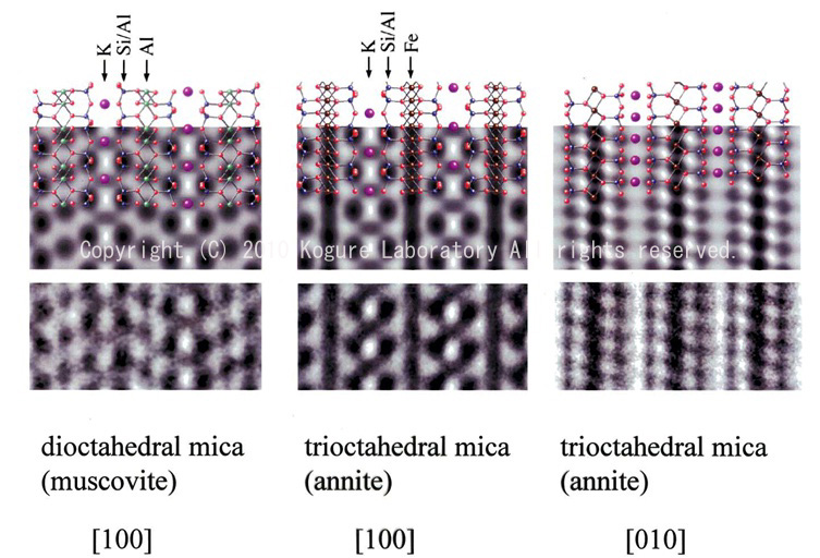
Simulated HRTEM contrasts (top) and corresponding experimental images (bottom) of micas
Simulation program: MacTempas, acceleration voltage: 200kV, Cs: 0.5mm, spread of focus: 10nm, beam convergence: 1mrad, specimen thickness: 2.5nm, defocus value: -40m. TEM used: JEM-2010UHR
Kogure, T.: "Investigation of micas using advanced TEM." in: Micas: Crystal Chemistry & Metamorphic Petrology, Reviews in Mineralogy and Petrology Vol. 46, Mineralogical Society of America, Washington, D.C., (2002) 281-312.
![]()
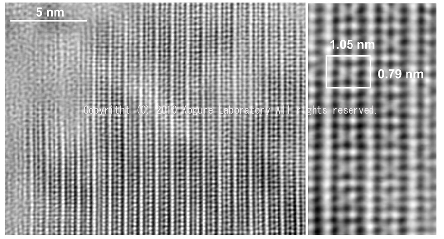
2. HRTEM image of muscovite recorded along <100>
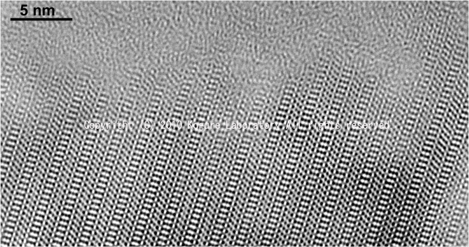
HRTEM image of muscovite (KAl2Si3AlO10(OH)2) recorded along <100>, using JEOL JEM-2010UHR at 200 kV.
(unpublished data)
![]()
3. Time –resolved HRTEM images of biotite recorded along Xi-axis
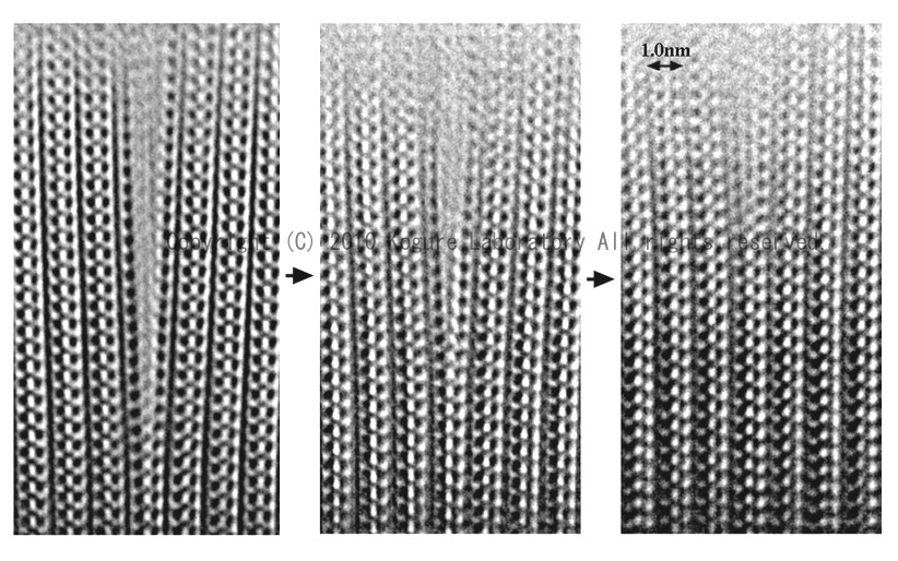
Time –resolved HRTEM images of biotite recorded along Xi-axis, showing that a micro (001) cleavage is being extinguished by electron radiation.
Kogure, T.: "On the structure of cleaved surface in biotite", Mineral. J., 19 (1997) 155-164.
![]()
4. HRTEM image of illite-1M recorded along [100]
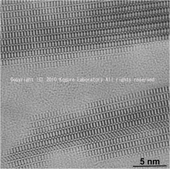
HRTEM image of illite-1M recorded along [100], showing a stacking fault by layer rotation near the bottom of the image.
(unpublished data)
![]()
5. HRTEM image of aspidolite, Na-analogue of phlogopite, recorded along Yi-axis
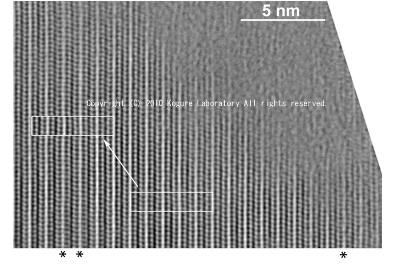
HRTEM image of aspidolite, Na-analogue of phlogopite, recorded along Yi-axis. The interlayers indicated with the asterisk are those occupied by potassium instead of sodium, which has a slight larger spacing than others.
Kogure, T., Y. Banno and R. Miyawaki: "Interlayer structure in aspidolite, the Na analogue of phlogopite", Eur. J. Mineral., 16 (2004) 891-897.
![]()
6. HRTEM image of lepidolite, a lithium-bearing trioctahedral mica, recorded along Yi-axis
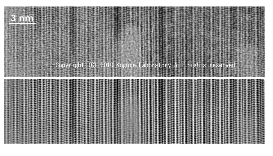
HRTEM image of lepidolite, a lithium-bearing trioctahedral mica, recorded along Yi-axis. The top is the original image and the bottom is the noise-suppressed one by image processing. Imaging along this direction shows considerable stacking disorder, suggesting that various n60° rotations occur in the structure.
Kogure, T. and M. Bunno: "Investigation of polytype occurrence in lepidolite by using Electron Back-Scattered Diffraction (EBSD) ", Am. Mineral., 89 (2004) 1680-1684.
![]()
7. HRTEM images of the planar defect in oxybiotite
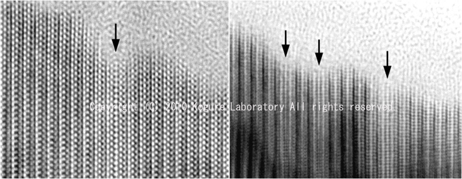
HRTEM images of the planar defect with a layer consisting of double tetrahedral sheets, or missing the central octahedral sheet, found in oxybiotite. (Left) image along Xi-axis. (Right) image along Yi-axis.
Kogure, T. and M. Nespolo: "Atomic structures of planar defects in oxybiotite", Am. Mineral., 86 (2001) 336-340.
![]()
8. HRTEM images of celadonite-1M, recorded along [100] and [310] from the same region
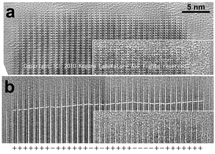
HRTEM images of celadonite-1M (K (Mg, Fe2+, Fe3+)2 Si4O10(OH)2), recorded along (top) [100] and (bottom) [310] from the same region. Stacking faults appear only in the bottom image, indicating that all stacking faults originate from 180° layer rotation in 1M stacking.
Kogure, T., J. Kameda and V.A. Drits : "Stacking faults with 180° layer rotation in celadonite, iron and magnesium-rich dioctahedral mica", Clays Clay Miner., 56 (2008) 612-621.
![]()
9. HRTEM image of a new 2:1 layer, formed by annealing celadonite at 800°C in air
HRTEM image of a new 2:1 layer, formed by annealing celadonite at 800°C in air. The image was recorded along Yi axis. Notice that the two tetrahedral layers are facing without stagger in the 2:1 layer.
Kogure, T., J. Kameda and V.A. Drits: "Novel 2:1 structure of phyllosilicates formed by annealing Fe3+, Mg-rich dioctahedral mica", Am. Mineral., 92 (2007) 1531-1534.
![]()